
Electrical Actuated Turnout
- langemat
- Jun 27, 2020
- 6 min read

Updated: Mar 11
An electrical switch point for Lego(R) tracks makes the conductor’s life much easier and more comfortable. The desire of such an electrical switch point exists latest with the introduction of the 9-volt track system and if you do some research, you can find some solutions for it, indeed. But what is the issue of all of them? They are big in size, or need customization, or can be used only on fixed train layouts, or need special (expensive) parts, or can be used only with a specific motor, or (and this is the most critical one for me, so we will go more into details soon) they add a lot of stress on the point switch mechanism, so soon or later it will fail. One of these concepts is the common and often copied mechanism with the gear rack. It pushes not only against the pins for the yellow ground throw but also against the slider below it and the back plate, while switching from one to the other turnout position (even if the gear axle is supported on both ends with a technic brick).

The picture above shows the basic principle of the electrical actuation and is only one example. There are different actuators (depending on the space you have) and motors possible.
So all the mechanism I could find didn’t work for me in one or another point and I was thinking about a new idea. It took me eight days of thinking, building, testing, redesigning and badmouthing until I found it. My requirements on the new electrical switch point mechanism were:

As you can see above, my solution doesn’t meet all the requirements, but most of them and so, I think, it’s the right time to share it with you.
It is a modular design, switch mechanism and drive unit are separated which allows the highest flexibility in arranging it. All switch mechanisms and drive units are combinable, so you can choose the best fit for your layout. Below you find an overview about the different switch mechanisms and the drive units and their pros and cons.

The picture above shows the switch mechanisms, I designed. All of them have their own benefits (see below) and with (very) small changes, they fit on right and left turnouts.
(1) The biggest of the three mechanisms allows the installation of the drive unit on the left or right side without any changes and a perfect and stable axle connection to the drive unit.
(2) The middle one is the smaller “brother” of (1) - in case lesser space is available. It allows the connection of the drive unit only on one side (small changes and the side can be swapped), but with the same perfect and stable axle connection to the drive unit.
The smallest of the switch mechanisms for very narrow space situations - or if you prefer the turnout mechanism should not get to much attention if you look at your layout. With only 4 x 5 studs surface, it is really small. But the medal has always two sides: The axle connection to the drive unit is only ½L axle, so it might require some support, depends on the position of the drive unit.
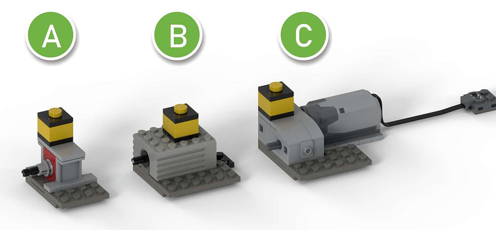
The picture above shows the different drive units for the switch points. The idea is, to use the older 9-volt system, as well as the newer Power Function elements. Also here, the target is as small as possible without compromise to stability and function. The yellow 2 x 2 brick on top is to mark the switch point with their respective number in your train layout, so it is easy to identify them.
(A) The drive with the 9-volt micro motor is actually just to show the possibility using it for the switch mechanism. I know the motor is very expensive if you want to buy it, but some of you might have one or another in your brick collection and since the drive with this motor is really small, I want to show it as well. But I have to highlight, that the switching speed is slow. An energy impulse will not be enough to move the point blade to the other side. You need to press the button longer to reach the other end position. But with the slow movement it looks more realistic too, so …
(B) The very common (and often too weak) 9-volt motor is doing a great job here, because my switch mechanisms do not need much power. The motor is easy to buy, not too expensive and the size is ok. And the 9-volt system gives an easy opportunity to bridge long distances (between drive unit and switch controller), so this drive is my favourite.
(C) Of course, a drive unit with a Power Function motor is a must - because many Lego enthusiasts will have them in their collection - and in my opinion, the M motor is the best choice, with reasonable size and its ability to put it straight on a plate. But like all Power Function motors, also the M motor is too powerful and so the use of a friction clutch is necessary, otherwise the mechanism will disintegrate and its parts fly around. Because of the friction clutch, the overall size of this unit is a bit bigger than the others. And I find it quite difficult to bridge long distances with the Power Function system which makes it for me not so convenient to use it, but maybe there is a solution out there.
Below you see a comparison between the switch mechanisms and the drive units in a simple spreadsheet, so it is easy to identify the pros and cons of each module.

Overview of pros and cons of each module.
Each switch mechanism is combinable with each drive unit. As a connecting element between both, I use a universal joint. So the location for the drive unit can be chosen very flexible and according to your needs. And if you prefer that, you can cover the universal joint connection as well.
As you can see in the first picture above, my mechanisms and drive units are placed opposite the yellow ground throw and switch slider, which answers the question, why I don’t need much power to change the turnout tongue position. The switch mechanism is in direct contact with the turnout blade. How it works, you can see at the end of this article in the video. As a detail, I designed a manual switch lever, where usually the yellow ground throw has his place. It is not moving with the tongue position; it just looks nicer than the yellow throw.

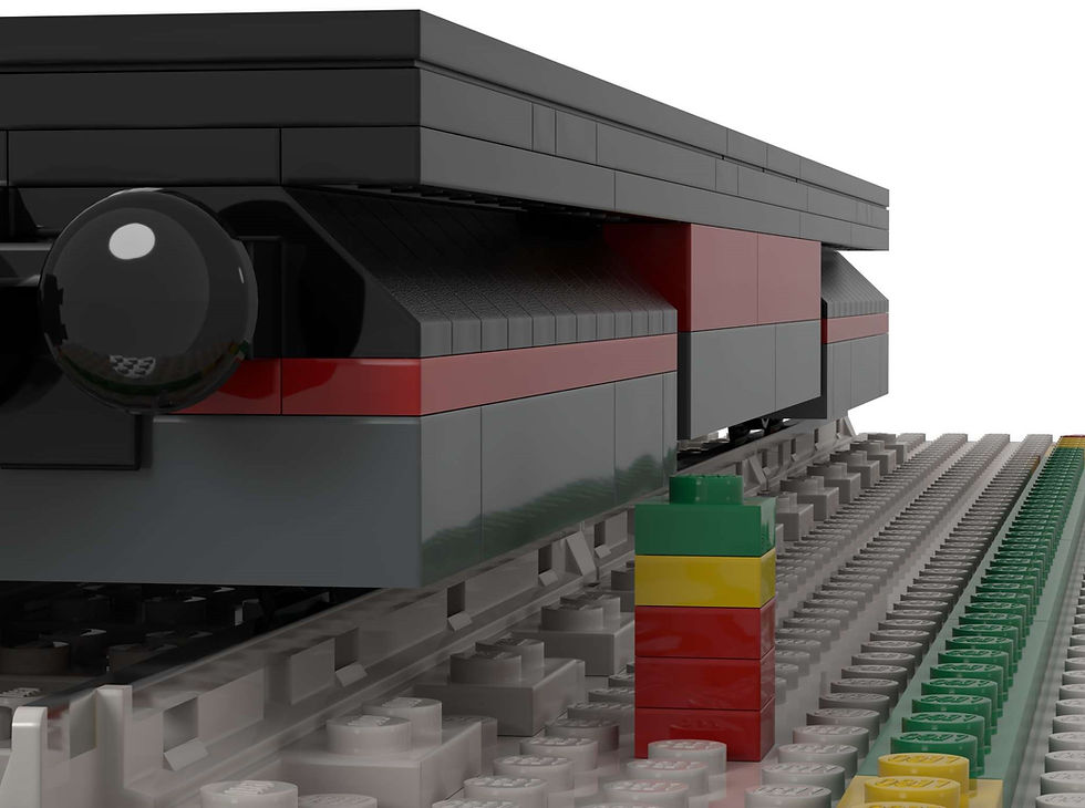
For you maybe most important is the question: Does the electrical switch work on my layout and can my train locomotives, cars and wagons pass it without crashing it or derail?
For that, I built a test car and tried it on any track constellation, I could think about. Below you can see the result.

So everything within the range of the test car above, is able to pass the switch mechanisms without any issue (length 40 studs, width 8 studs, green). Cars longer and wider than that (yellow and red) might have issues, depends on the individual design.
Bogies with details and addition elements higher than 1 brick and 1 plate (from the ground until the bogie element) will pass without issue.

Another critical element is the middle section of longer train cars and wagons because of their overhang in curves and turnouts. The minimum height of underneath elements in the middle section is 1 brick and 2 plates. Lower hanging elements might collide with the switch mechanism or the manual switch lever.
PLEASE NOTE:
The modules work very well with 9-volt tracks and turnouts combined with RC trains or with 9-volt trains. If you use 9-volt trains, you need to use my "Dead Track Wire Bridge" (see my other post in the BLOG section) to ensure the power supply to the turnout track. The switch point is permanently switched to "turnout" position, so the track on the "straight" position is "dead", because the switch point is always deactivating the opposite side automatically. The "Dead Track Wire Bridge" cancels this effect and the train can move on all tracks.
The modules will not work with RC tracks (100% plastic version) without modification. The reason is, that the RC turnouts do not have the hole on the side you need for the pin of the switch mechanism.
Video:
I provide a detailed step-by-step building instruction. At the end of it, you find an overview of all needed parts.
A print-ready sticker sheet is available too (in case the model contains stickers). I provide it in the widely used PDF-format in high-resolution and print-ready.
Furthermore, I provide the parts list in Excel format. This makes it easy to filter out needed parts and create order lists.
Disclaimer: I am not responsible for any damages or injury on parts and humans happen while following my instructions. Everything you do is your responsibility and under your personal risk.
Link to the instruction and sticker files:
Link to more pictures of the model:


Comments